Intro to LEDs Tutorial
Introduction
Light Emitting Diodes (LEDs) are a great way to get started with Arduino because they’re one of the simpler components to work with and you’ll use them in practically every other project your build. They’re essentially small lights, which you can turn on and off using code you write on the Arduino or they can be controlled indirectly by logic you build into a circuit.
Parts
Rather than buying these parts individually, you’re better off just getting a starter kit.
If you’re on a budget, this Arduino Starter has everything you need for this tutorial. If you’d rather spend a little more, but get a lot more, the Official Arduino Starter Kit is fantastic. You can also check out our review of popular starter kits if you want to dig in a little more.
Breadboards
We’ll want to use a breadboard to build our circuit. Breadboards and jumper wires allow you to quickly make non-permanent connections between components. They’re used constantly while prototyping, because they make it easy to undo mistakes.
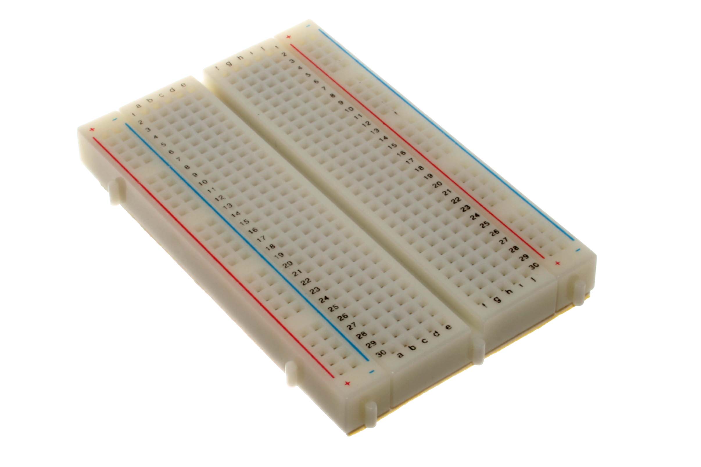
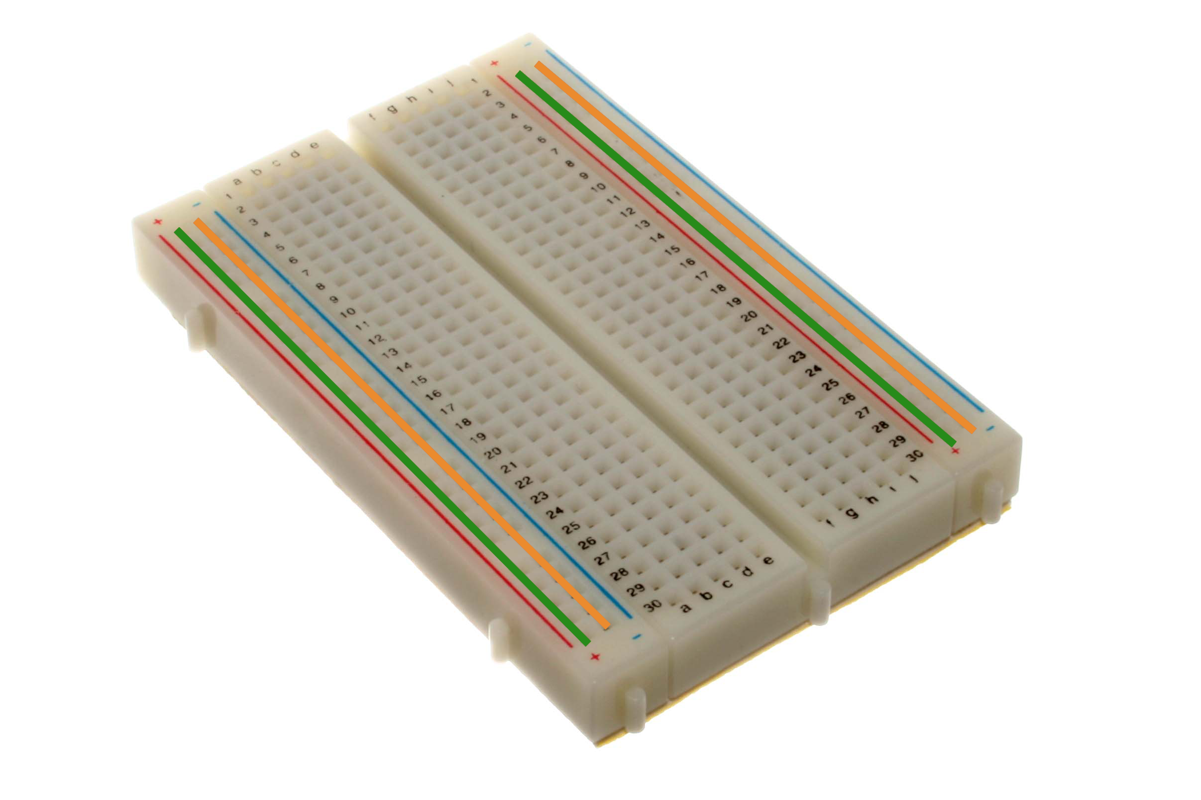
Breadboards usually have two long vertical columns of holes on each side of the board labeled with a plus and a minus. Every point on each column is connected to every other point in the same column, like this:
Similarly, each row is connected as well:
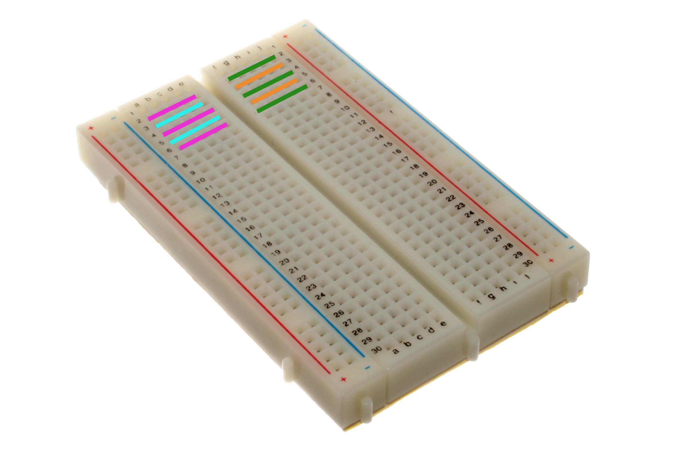
Note that no connections go over the center line. This allows you to plug in DIP chips that have two sets of pins without connecting the pins from each side together.
How to Blink an LED
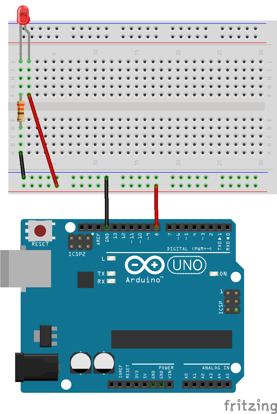
Here’s a detailed explanation of how the current is flowing in this circuit:
- Our code tells the Arduino to turn pin 8 on.
- Current begins to flow down the red wire.
- The current travels down the power rail to the next red wire.
- The current travels across that red wire and into a row on our breadboard.
- The current travels across the breadboard row and into the Anode of the LED.
- The current passes thru the LED, causing photons (light) to be emitted.
- The current exits the LED using the Cathode.
- The current travels across the breadboard row and into the resistor.
- The resistor limits the flow of current across it. Think of this like a traffic jam - it slows down all the traffic behind it.
- The current exits the resistor, travels across the breadboard row toward the black wire.
- The current travels across the black wire, and down the power rail.
- One last hop across the black wire and our current has reached Ground.
This animation shows the path that the current follows:
We’re using a 330Ω resistor, which is a good starting point for most LEDs. Using a smaller value resistor will increase the brightness of the LED (by allowing more current to pass thru) but you run the risk of burning out the resistor by allowing too much current to flow through it. If you’re feeling ambitious, read up on Ohm’s Law to learn how to calculate the proper resistor value.
Code
This is a simple program that turns the LED on and off every second.
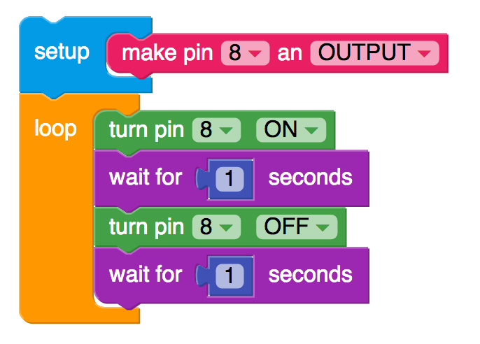
Experiment with the delays and see what kinds of patterns you can make.